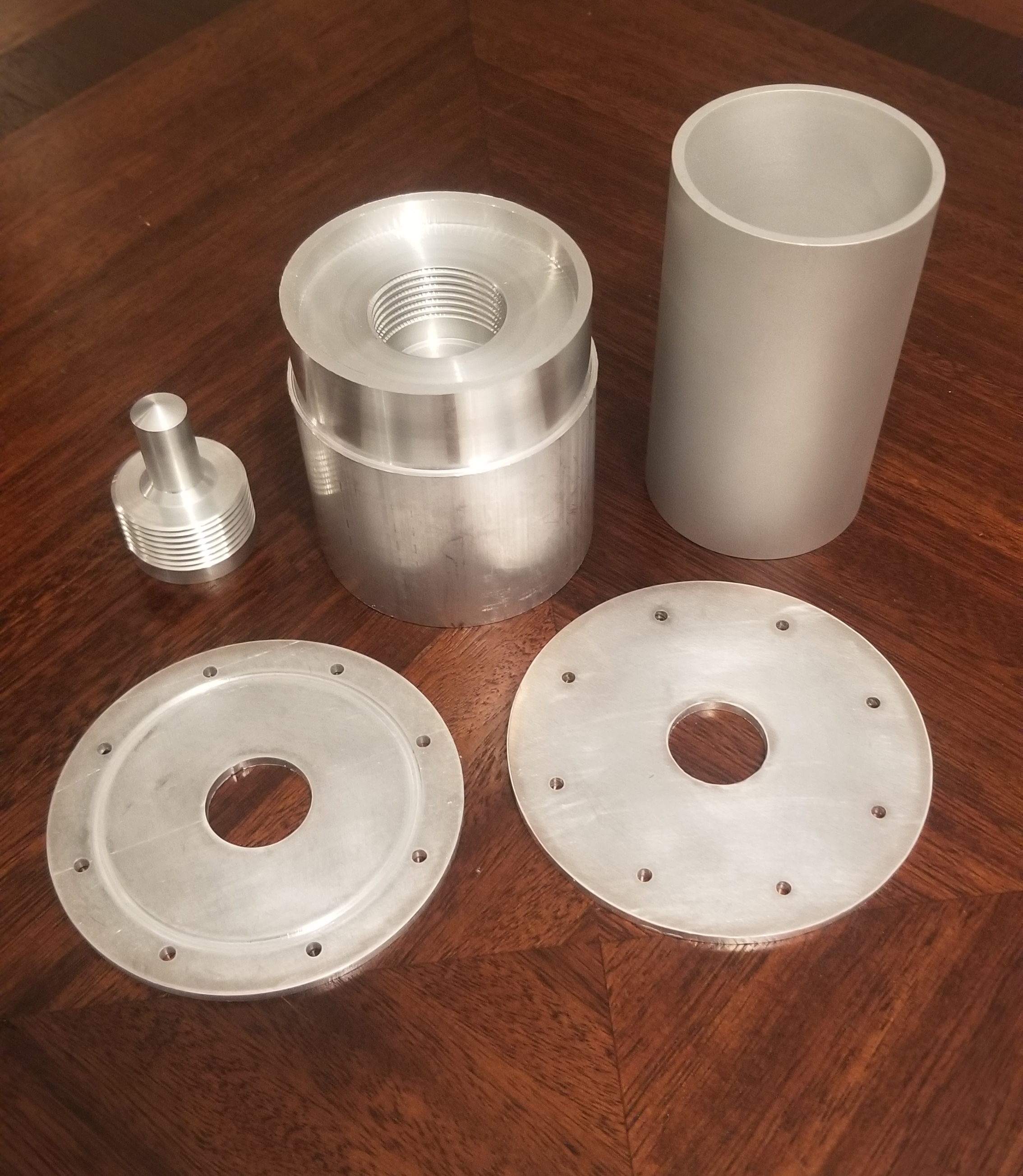
This weekend marks the initial assembly of the test rocket. If you take a look at the pictures, everything looks pretty clean. Well, the pictures make it look a lot more effortless than it turned out to be. The initial attempts at welding went… poorly. I had machined a simple welding fixture to keep everything in place when I gave the parts to the welder. Unfortunately, the weld went through in multiple places, securing both the rocket and the fixture in place. After chiseling and boring away for a few hours — all but destroying the original pieces — I realized that I probably needed to machine new parts and start over.
I cut off the failed weld from the combustion-nozzle assembly flange. I was able to salvage most of this piece. However, both flanges and the injector dome had to be machined all over again. As I already had both material and the CAM programs available, this was not nearly as daunting as it first seemed. Within two weeks I had remade the parts and prepared for a second welding round. I discussed what might have gone wrong with the welder, and we made a plan to improve on some of our methods. I added an inset to the flange rather than attempting to fixture it from the inside. The welder thought this and a slower weld process would have better results.
As you can see, the methodology improvements paid off! After receiving the parts back from the welder (which they were kind enough to do free of charge!), I did some final machining on the welds to clean up the finished appearance. I drilled the flange holes to the proper size to accommodate #6 bolts. Finally, I drilled and tapped two holes (1/8″ NPT) for the instrumentation on the combustion chamber.
The end product looks great given the difficulties I have had to get to this point! I’ve learned a lot of lessons putting this together, as painful as some of them were. It’s not perfect, but it’s in good shape to gear up for a test in a few months. There are a few minor final assembly activities (fitting O-ring, etc), but the bulk manufacturing for the rocket is now complete!
Now that the rocket is complete, I have turned my attention to the test stand. We have been collecting pressure transducers, thermocouples, load cells, and all of the fun instrumentation! The plans are coming together for this, and some parts are already ordered. I don’t expect the test stand will take much longer than a month to complete at the current pace. I’m tentatively shooting for an April test fire. We’ll see how that plays out.
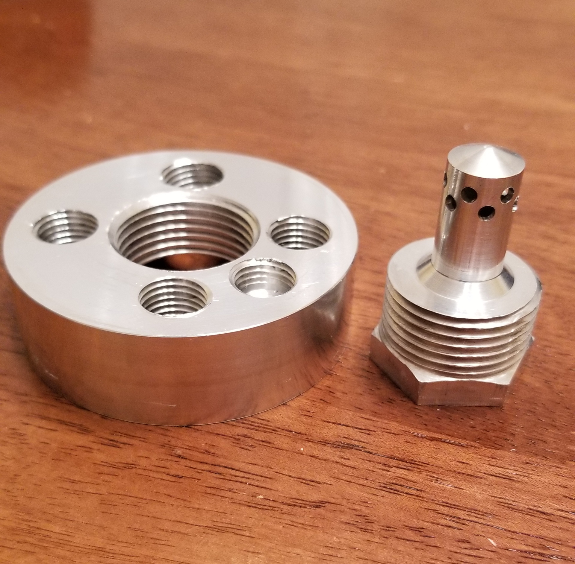
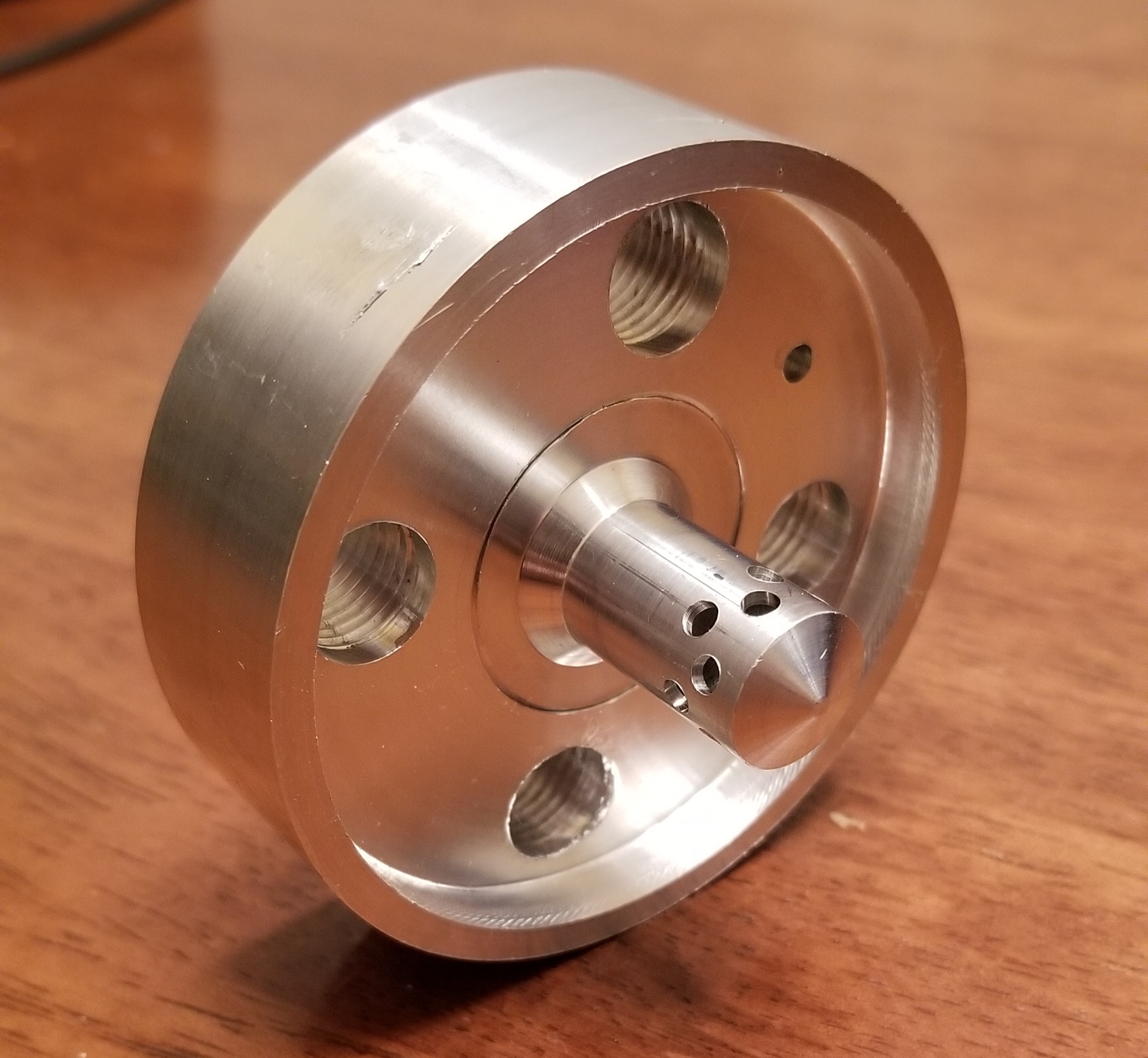 ded to the body, we can swap the pintle out easily and collect performance data for each. The fuel-air throat areas can be easily altered by changing the pintle OD and injector hole diameters. The number of injector holes can also be optimized, although as they become smaller, they begin to pose a manufacturing challenge.