The Plan
For this post, I would like to step back a bit from the typical software discussion, and provide a little insight into my latest hardware project (okay, there is some software!). Over the last few years, my friend and I have been designing components for a small, hobbyist-level liquid rocket engine. We had a few goals in mind when we started, and trust me when I say they were quite lofty:
- Generate “some” thrust — maybe 50 lbf
- Replaceable injector for design iteration
- Don’t get burned
Okay, so they were actually pretty basic. The first thing we did to work towards achieving this goal was break the task up into several iterations. The first iteration happens to be a glorified propane-air torch that also has a “kick” to it. Perhaps the coolest feature of the rocket is the replaceable
injector, which is based on a coaxial pintle design. In preparation for the next iteration of the rocket, we will test various pintle designs to optimize performance and reduce the number of parts that will have to be remade. These can later be integrated into the injector dome when performance properties have been measured and confirmed.
The Challenge
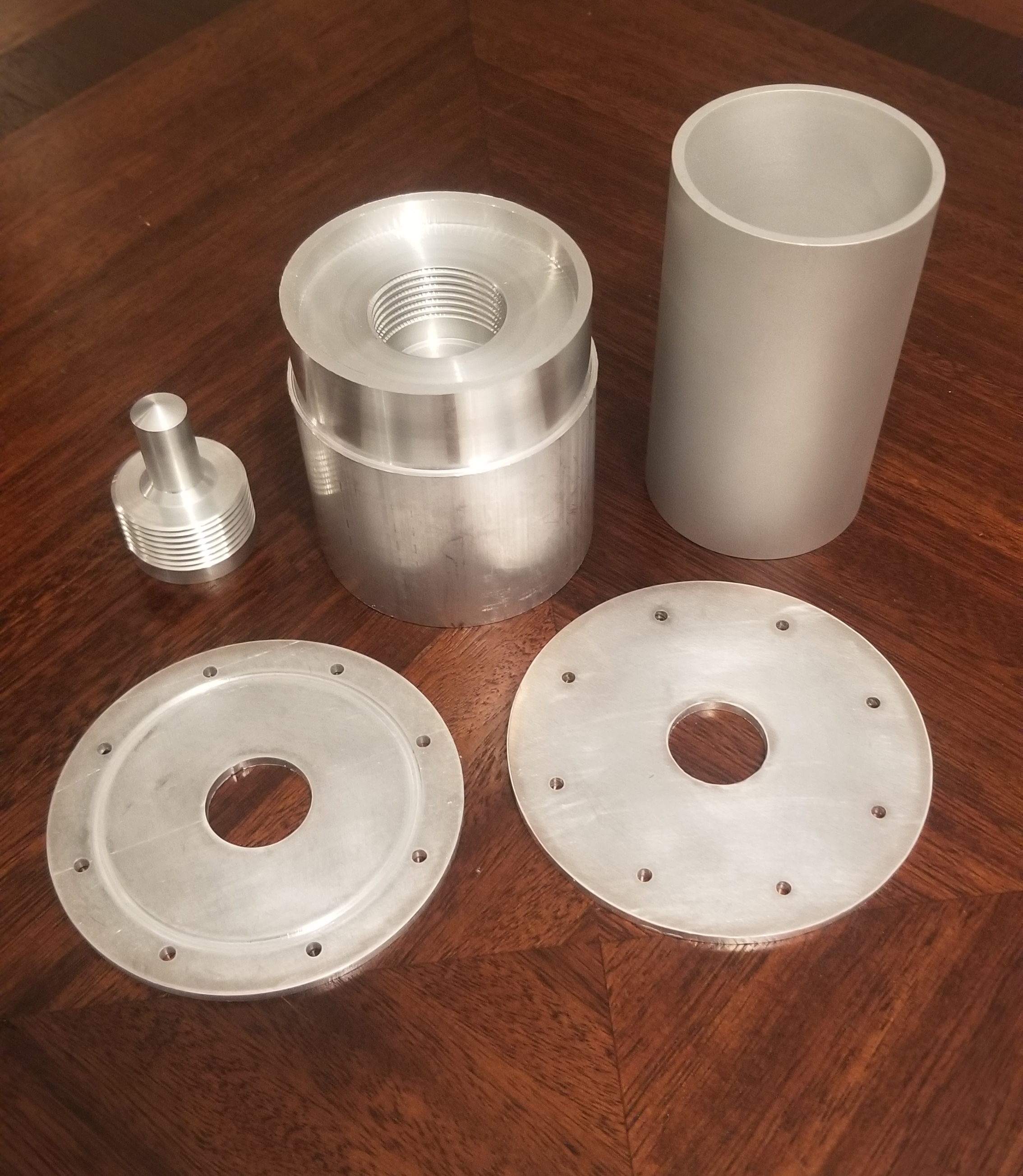
One of our early challenges was manufacturing. After we had created the drawings for each component of the engine, we set out to collect some quotes and get some parts made. It turns out that machine shops charge exorbitant prices for one-off parts. It was about half as expensive to have the parts made in aluminum, so we had the shop start with the throat/nozzle. Of course, this change in material meant that combustion would have to be largely undersized, and the burn times would have to be drastically reduced. For this iteration of the motor, we decided, these were acceptable tradeoffs.
However, the price did get me looking for alternatives. I found a local maker space that offered access to their CNC mill and lathe for a very reasonable monthly cost. I figured that by the time I learned to machine the parts myself, I would still come out ahead. And so I have spent the last few months between my space simulator project and my day job learning how to machine and perfecting my methods. I am just now beginning to complete the final set of parts for the rocket. We hope to have these ready to be welded in the next few weeks.
Pintle Details
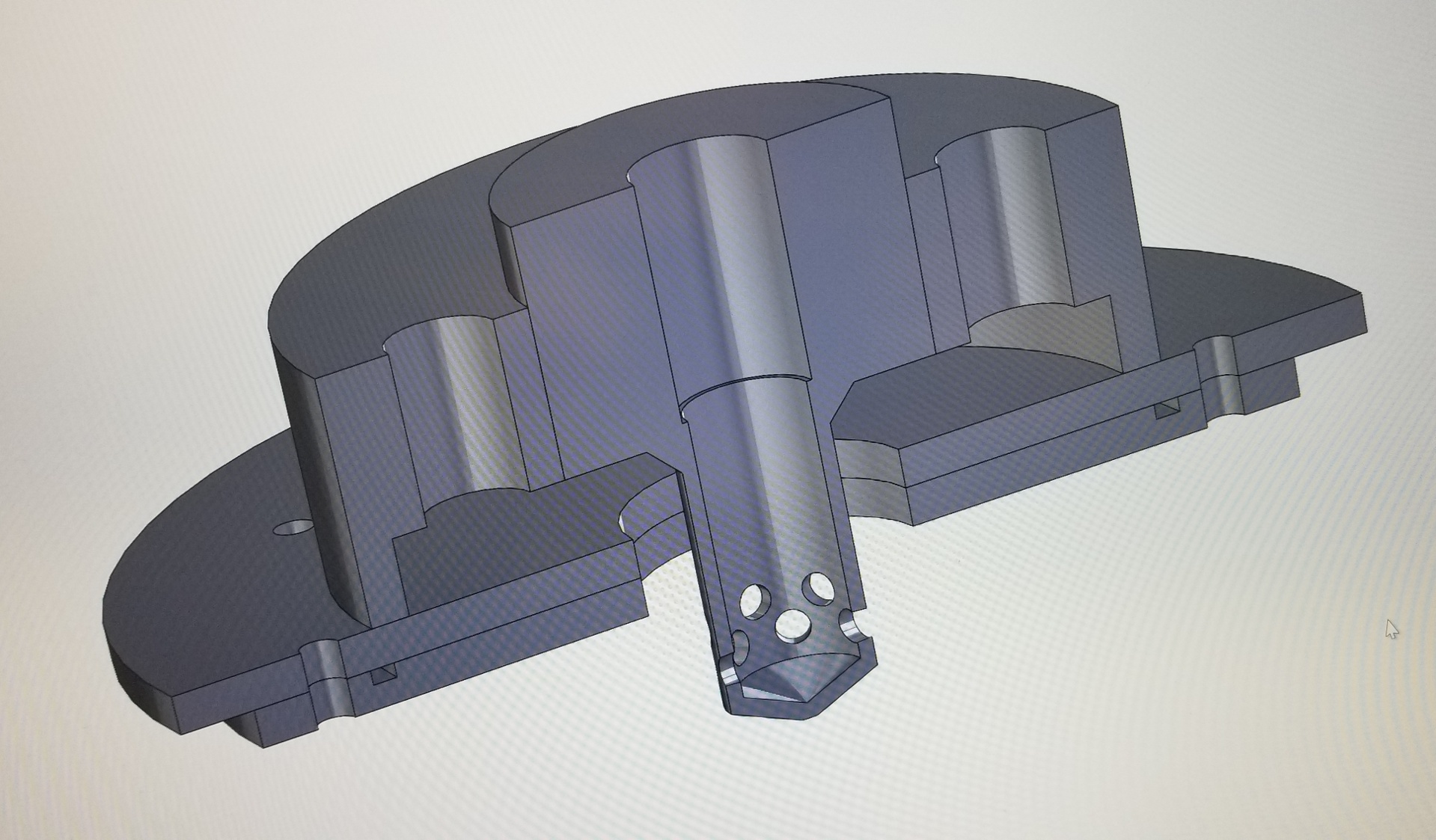
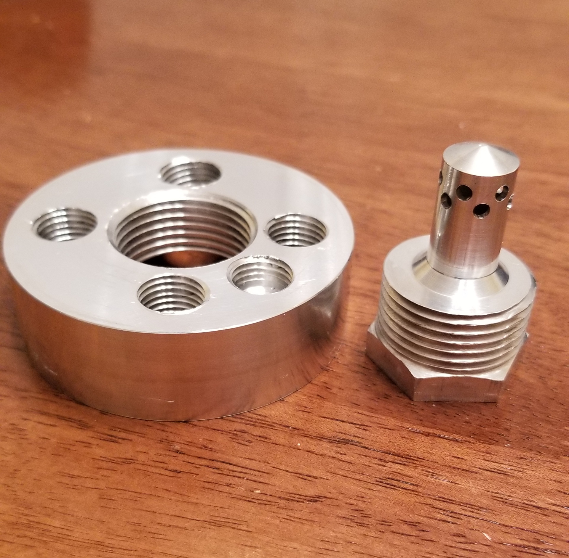
The pintle is really the star of the show. This device is easy to manufacture, and provides excellent mixing characteristics. The concept is simple: inject the fuel (in this case propane) radially from the center tube (known as the pintle). Flow the oxidizer (air) through a concentric opening traveling perpendicularly to the fuel. The two propellants collide and ideally atomize as they travel through the combustion chamber.
Because this is threa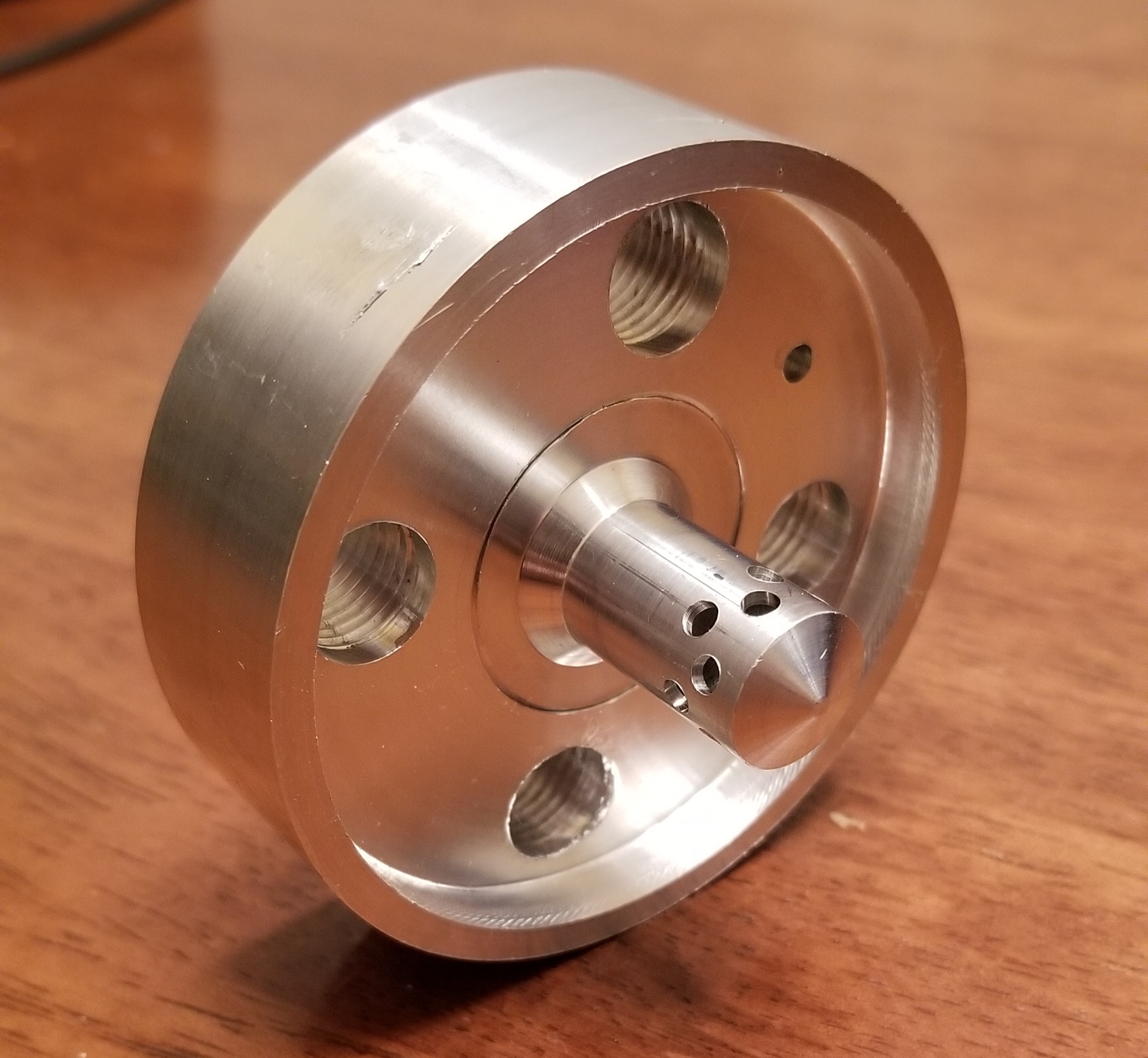 ded to the body, we can swap the pintle out easily and collect performance data for each. The fuel-air throat areas can be easily altered by changing the pintle OD and injector hole diameters. The number of injector holes can also be optimized, although as they become smaller, they begin to pose a manufacturing challenge.
Conclusion
I hope to dive into some details about the rocket as it gets closer to completion. We are moving towards constructing the test stand and software to support the static fire. If the rocket can be assembled by March, I hope to have the first hot-fire test as early as April or May. As always, stay tuned and we’ll see where this goes!